
Home / Machines / Spinner Hanger Shot Blasting Machine for LPG Cylinder Descaling
Spinner Hanger Shot Blasting Machine for LPG Cylinder Descaling
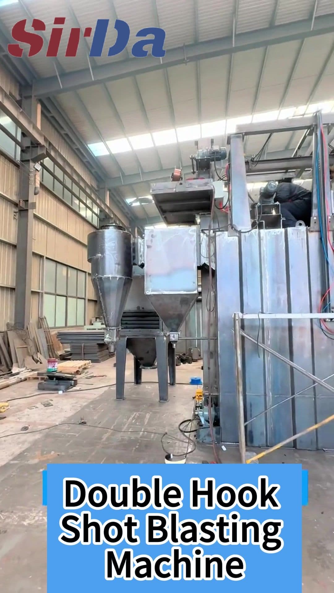
A spinner hanger shot blasting machine for descaling LPG gas cylinders: parts are suspended from a rotating spindle and indexed through fixed blast positions, so every shell is cleaned on all faces without changing the fixture. Batch cycle cleaning for gas cylinder refurbishment, valve and thread masking, and steel shell preparation.
PREPARE FOR
WHAT’S NEXT.
Match workpiece handling, blasting configuration and production flow to your application.
Request a quotationWhy gas cylinders are a different cleaning problem
LPG cylinders are welded steel pressure vessels, and the material sitting on the shell is not a single layer of dirt. It is usually a combination of mill scale left from shell forming, rust bloom from outdoor storage, and remnants of the coating or protective film applied at the factory. Each of these responds differently to abrasive, and each of them has to come off before the shell can be inspected, painted, or put back into service.
The geometry makes the problem harder than a typical batch of castings or brackets. A cylinder wall is thin relative to its diameter, so aggressive blasting that would be harmless on a solid part risks cutting into the parent metal and destroying the wall thickness the pressure vessel depends on. At the same time, the neck, the valve seat, the threaded connection and the stamped inspection marks cannot be touched at all. A general-purpose fixture puts the operator in charge of masking, and manual masking on a cylinder is both slow and inconsistent.
The spinner hanger arrangement removes the operator from that decision. Cylinders are suspended from a spindle at fixed intervals, and the spindle indexes through fixed blast positions rather than the operator swinging the part. Every cylinder in a load sees the same exposure, so the result does not depend on how the work was stacked or who was on shift.
How the machine works
A load of cylinders is hung onto the spindle through the valve end, spaced so that neighbouring shells cannot strike each other during indexing. The blast cabinet holds a bank of nozzles aimed at the working zone, and the spindle rotates through a set number of index positions before stopping. Between the blast cycle and the next index there is a short settling and dust extraction interval, so abrasive that has come off the shell is drawn away before the part is repositioned.
After the last position the spindle presents the load for unloading, and the same fixture is used on the way in. Because the load is handled as a fixture rather than as individual parts, the machine suits production in defined batches: a known number of cylinders per cycle, a repeatable cycle time, and a separation between loading, blasting and unloading that can be arranged to suit the floor layout.
The cabinet is fully enclosed, with the spindle position, blast duration and dust extraction driven by the control so a cycle can be repeated on the next batch with the same settings. Airflow is maintained inside the cabinet so that dust is captured at source instead of being carried into the working area.
What this arrangement protects
- Wall thickness — the distance from the shell to the blast media is fixed by the spindle geometry, so the energy delivered to a cylinder is consistent from the first hook to the last.
- Neck, valve and threads — the valve end is masked at the fixture level, so the operator is not inventing a masking method on the shop floor for every load.
- Uniform result across the load — indexing through fixed positions gives every cylinder in a batch the same number of exposures in the same directions.
- Operator distance from the process — loading and unloading take place outside the cabinet with the door closed, keeping hands away from moving abrasive and from the rotating spindle.
- Dust containment — enclosure with extraction at the blast zone limits airborne abrasive around the working area.
What to confirm before we size the machine
The machine is configured around the cylinder, not the other way round, so the following has to come out of your drawings and your downstream process:
- Cylinder diameter, overall height and straight-shell length, including the range across your product mix
- Neck and valve thread standard, valve type, and whether cylinders arrive with valves fitted
- Whether the valve, thread, label area and stamped inspection marks must be masked, and how masking is currently handled
- Condition to be removed: mill scale, storage rust, old paint, or a combination, and how much of the shell needs to come back to metal
- Downstream requirement after blasting, such as the coating or inspection standard the cleaned shell has to satisfy
- How many cylinders per cycle and how many per shift, which sets the batch size and the loading arrangement
- Incoming and outgoing handling, such as conveyor interfaces, crane or hoist availability, and stacking requirements on discharge
Once those are agreed, the spindle spacing, nozzle arrangement, cabinet size and cycle programme are fixed against your actual parts. Any capacity figure quoted before that conversation would only be a guess.
DEFINE THE CONFIGURATION.
- Workpiece
- Please confirm cylinder type and material
- Cylinder range
- Please provide dimensions across your product mix
- Neck and valve
- Please confirm thread standard, valve type and masking
- Loading
- Please confirm quantity per cycle and per shift
- Condition to remove
- Please describe the surface condition to be removed
- Downstream requirement
- Please state the required downstream standard
- Handling
- Please confirm incoming and outgoing handling
BRING US YOUR WORKPIECE.
Share a photo or drawing, material, maximum dimensions and expected output. These details help us review a suitable configuration.
Send project requirements