
Home / Machines / Rotary Hook Shot Blasting Machine for Forgings and Irregular Parts
Rotary Hook Shot Blasting Machine for Forgings and Irregular Parts
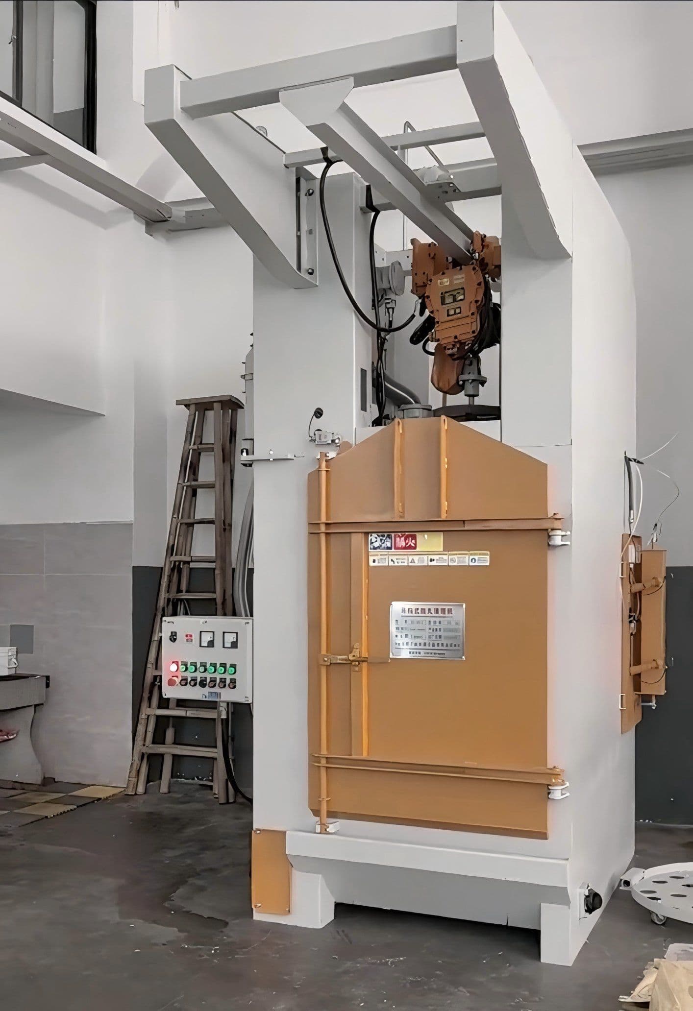
A rotary hook shot blasting machine combines the revolution of the hook arm with the spin of the workpiece, so every point of a forging surface passes periodically through the blast jet and the shadow band left by a fixed blast source disappears.
PREPARE FOR
WHAT’S NEXT.
Match workpiece handling, blasting configuration and production flow to your application.
Request a quotationWhy a forging rotates instead of passing through
The surface of a forging is not flat. A crankshaft has journals and a counterweight, a gear has a tooth root and an internal bore, a flange has a back face and pass-through holes. Those geometries impose one consequence: if the blast source is fixed and the workpiece does not move, every direction masked by the workpiece itself becomes a band the treatment never reaches.
The width of that band is not a design parameter, it follows from geometry: the distance between the masking feature and the surface, multiplied by the divergence angle of the jet. The taller the workpiece and the further the obstruction sits, the wider the band. In manual blasting, the operator keeps turning the part over to close it. On an automatic machine, without a trajectory deliberately designed to compensate for it, the band stays exactly where it was.
The logic of the rotary hook is not "spin the workpiece faster", it is to give the workpiece two independent motions: the hook arm describes a revolution around the workpiece centre while the workpiece simultaneously spins on its own axis in the hook. As the two motions add up, every point on the surface passes periodically through the centre of the jet — not roughly covered, but genuinely presented to it on every load.
It is worth setting this against a rotary table. A rotary table provides rotation on the spot only: the workpiece does not revolve, and a single jet pass covers only part of the circumference. In a rotary hook, revolution and spin coexist. The rotary table suits parts of regular geometry where only the outer diameter matters; the hook suits forgings, where each face points somewhere different.
What the two-axis motion actually delivers
- No shadow band — the revolution carries the workpiece to the jet while the spin presents one face after another. Both are required: without revolution the orientation never changes, without spin the workpiece merely turns in front of a fixed source.
- No dedicated centring tooling — the hook is a generic part. The workpiece is simply hung and processed, with no adjustment for its turning radius or height, unlike a rotary table whose fixtures are set up for each series.
- One machine for several workpiece families — you change the hook, not the machine. Forgings, gears and gas cylinders can run on the same line, and the cycle is set by the size of the part rather than by the structure of the machine.
- An already proven abrasive circuit — the turbine, separator and recirculation follow the same logic as suspended machines. Shot flow and circulation speed are defined per workpiece, with no new principle introduced.
Where it fits, and where it does not
The rotary hook fits forgings, gears, crankshafts and annular parts that need treatment over the whole circumference or the whole surface, especially those with flanges, steps or irregular shapes.
In the cases below, a different solution is needed, because the rotary hook cannot deliver it:
- Parts requiring treatment inside bores or at the bottom of a blind hole — the jet only acts from the outside; special nozzles or an endoscope-type device are required.
- Different finish requirements on different zones of the same part — a single rotation cycle cannot apply a different intensity per zone.
- Very light or very thin parts that could deform on the hook — the weight of the hook itself and the dynamic forces at the hanging point can exceed the stiffness of the part.
- Unit weight beyond the capacity of the arm and the drive — overload produces an uneven revolution, which worsens the very shadow-band problem the machine is meant to solve.
Arm dimensions, revolution and spin speeds, abrasive selection and the finish standard can only be settled after examining the dimensions, weight, geometry and surface requirement of the actual part. A drawing or a sample is what allows a verifiable configuration to be prepared.
DEFINE THE CONFIGURATION.
- Workpiece
- Forgings, gears, crankshafts, annular parts and other irregular-geometry components
- Handling
- Hook suspension; arm revolves around the workpiece centre while the workpiece spins on its axis
- Surface removal
- Mill scale, rust, moulding sand, old paint and burrs
- Control
- Automatic PLC cycle; revolution and spin speeds confirmed per workpiece
- Configuration
- Defined after reviewing workpiece dimensions, weight, geometry and finish requirement
- To be confirmed
- Workpiece dimensions, unit weight, hanging point, whether internal cavities need treatment, target surface level
BRING US YOUR WORKPIECE.
Share a photo or drawing, material, maximum dimensions and expected output. These details help us review a suitable configuration.
Send project requirements