
Tumble belt versus mesh belt: which conveyor fits the part
Tumble belt and mesh belt machines both carry parts through an abrasive stream, but they buy their result in opposite currencies. Tumbling exposes every surface by moving the part and pays for it in collision damage; a supported mesh belt protects a cosmetic finish by holding the part in place and pays for it in shadowing and belt wear. This guide works from part geometry - impact tolerance, blind bores and parting lines, wall thickness, size envelope, mix stability - through the arithmetic of a fixed drum batch versus continuous belt exposure, and into the failure modes each machine brings: run-off, broken wires and embedded scale on the mesh side, liner wear and door seal leaks on the drum side.
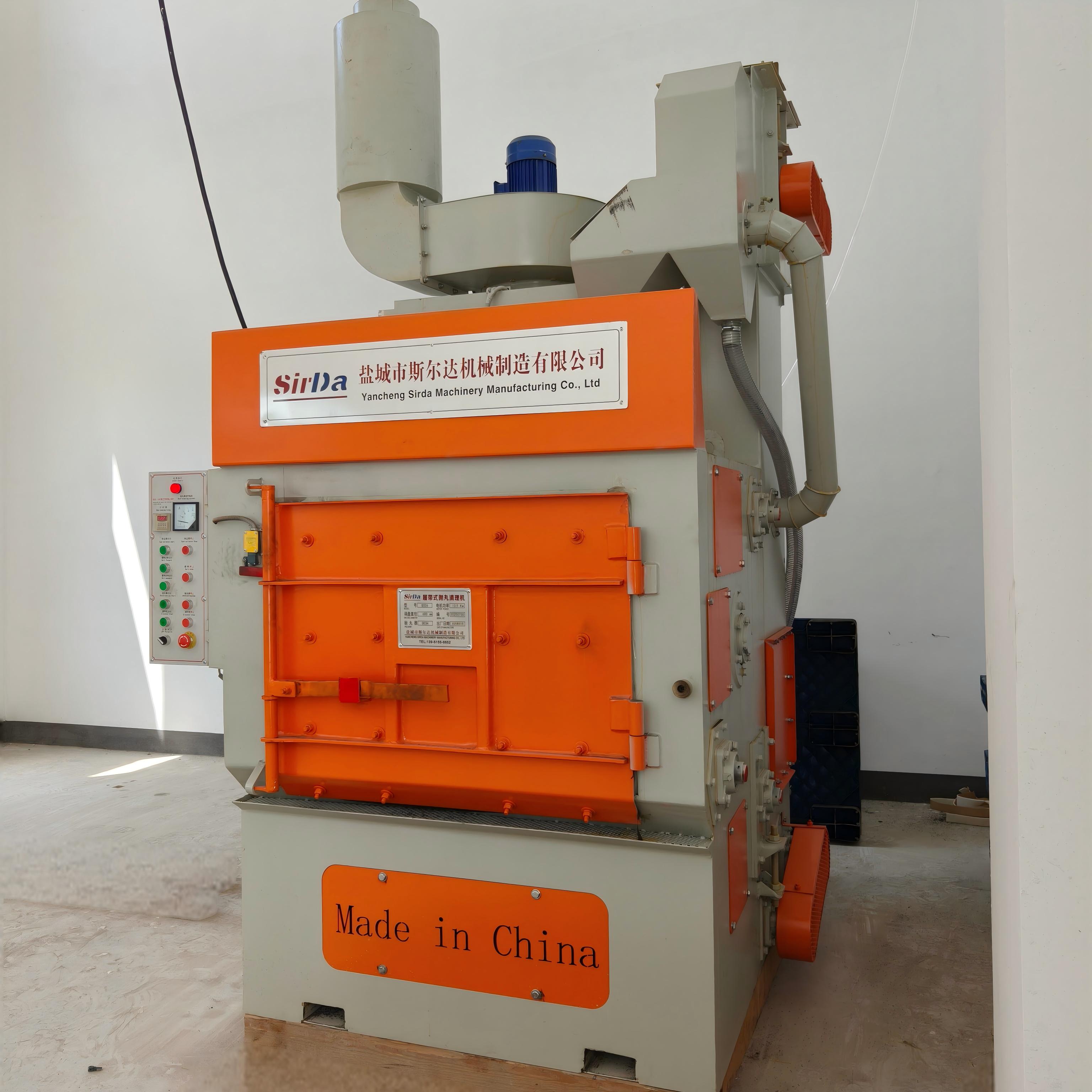
A tumble-belt machine is a batch machine. Parts are loaded into a rubber- or metal-clad belt drum, the drum rotates, and the charge tumbles through the blast stream for a fixed cycle. When the cycle ends the door opens and the parts come out. But no part held a defined position during blasting. Coverage comes from movement.
A mesh-belt machine is a through-feed machine. A woven or welded steel belt carries each part in a single layer, at a controlled speed, past blast wheels mounted above, below and beside the belt. Position is fixed and repeatable, and coverage comes from the wheel layout plus how the part was placed on the belt.
That single distinction explains almost every practical difference between the two families. Tumbling buys coverage by moving the part and pays for it in collision damage. A supported belt position buys part protection by holding the part still and pays for it in shadowing and belt wear.
What the part geometry decides
Run this decision from the part, not from a throughput number. Five things actually drive it:
- Collision tolerance - can the part survive being struck by another part? Bright aluminium, thin-wall castings, plated and pre-painted components generally cannot. Machined steel, foundry blanks and forgings usually can.
- Blind geometry - deep bores, parting lines, internal channels and inverted pockets. Only tumbling presents those surfaces to the stream reliably, without booking a second manual pass.
- Wall thickness and stiffness - thin sections deform inside a tumbling charge even when they survive contact, and a belt-supported position does not load them that way.
- Size envelope and load per piece - small to medium, mixed-charge work belongs in a drum. Long, wide or heavy pieces sit outside the useful belt envelope and belong on a roller conveyor or a hanger system.
- Mix and changeover frequency - a drum takes a mixed charge with no penalty. A belt wants parts of similar footprint, and mixing sizes on a belt creates both jamming and mutual shadowing.
Two points are easy to miss. First, cosmetic surfaces reverse the logic: a belt preserves the finish, while a tumbling charge leaves the dents and scuffs that only show up after plating or powder coating. Second, bottom-side cleaning on a mesh belt is not automatically solved by adding a lower wheel. The belt shadows part of the footprint itself, and in-process part rotation or a manual second pass is often the honest answer.
Cycle time, loading density and belt speed
The two machines are governed by different arithmetic.
A drum is a fixed cycle. Add loading and unloading, doors opening and closing, and your takt is the cycle plus handling. Inside the drum, fill ratio matters more than most buyers expect. A charge packed too full cannot cascade, so parts sit in the top layer and the corners stop getting cleaned; a charge too loose lacks the mass to carry abrasive into the crevices. In practice the drum is tuned for a fill that lets the charge roll rather than slide, and the cycle is then extended until the heaviest part in the batch is clean.
A belt is a continuous exposure calculation. Exposure time is the working length of the blast zone divided by belt speed, so the machine is dimensioned by how many seconds a part must see the stream. Loading density decides what the wheel actually hits: gaps between parts let abrasive reach the sides, while parts touching or stacked shadow each other permanently. Keep the charge single-layer with lateral clearance, and set belt speed to the surface condition you need - faster for light oxide removal, slower when a profile or a peening effect is required.
Neither number exists in isolation. Below a certain annual volume the changeover loss of a continuous line consumes the throughput advantage; above it, batch handling becomes the constraint. That threshold belongs to your own part mix and should be evaluated against it rather than against a catalogue figure.
Failure modes you will actually meet
Mesh belts fail in characteristic ways, and most of them trace back to how the line is loaded:
- Run-off, or tracking - usually caused by one-sided or uneven loading, idlers worn to different heights, or mismatched take-up. Correct the root cause instead of pulling the belt back with the tension screw.
- Broken wires - sharp stamping burrs, weld seams and flash riding directly on the mesh, plus shot trapped in the openings being struck again on every pass. Clearance under sharp parts and a working discharge blow-off prevent most of it.
- Bottom-wire wear - running a lower wheel at full power under thin, light parts hammers the belt from underneath for an entire shift.
- Tearing at inlet or outlet - a jammed or bent part dragged out by force instead of stopped. Anything caught must be cleared by hand with the drive isolated.
- Embedded scale - heavy oxide and slag lodged in the mesh behave like abrasive paper on the wire. A regular blow-down schedule is far cheaper than a belt replacement.
Drum machines fail differently: abraded or cracked belt and liner, door seal leakage that releases abrasive and dust into the room, denting of thin-wall parts against each other, and bridges in mixed charges that will not discharge cleanly when the door opens. Both families share the boring failures - worn blast wheel blades shifting the throw pattern, a separator no longer removing fines, and dust collectors whose rising differential pressure quietly chokes the airflow.
When neither machine is the answer
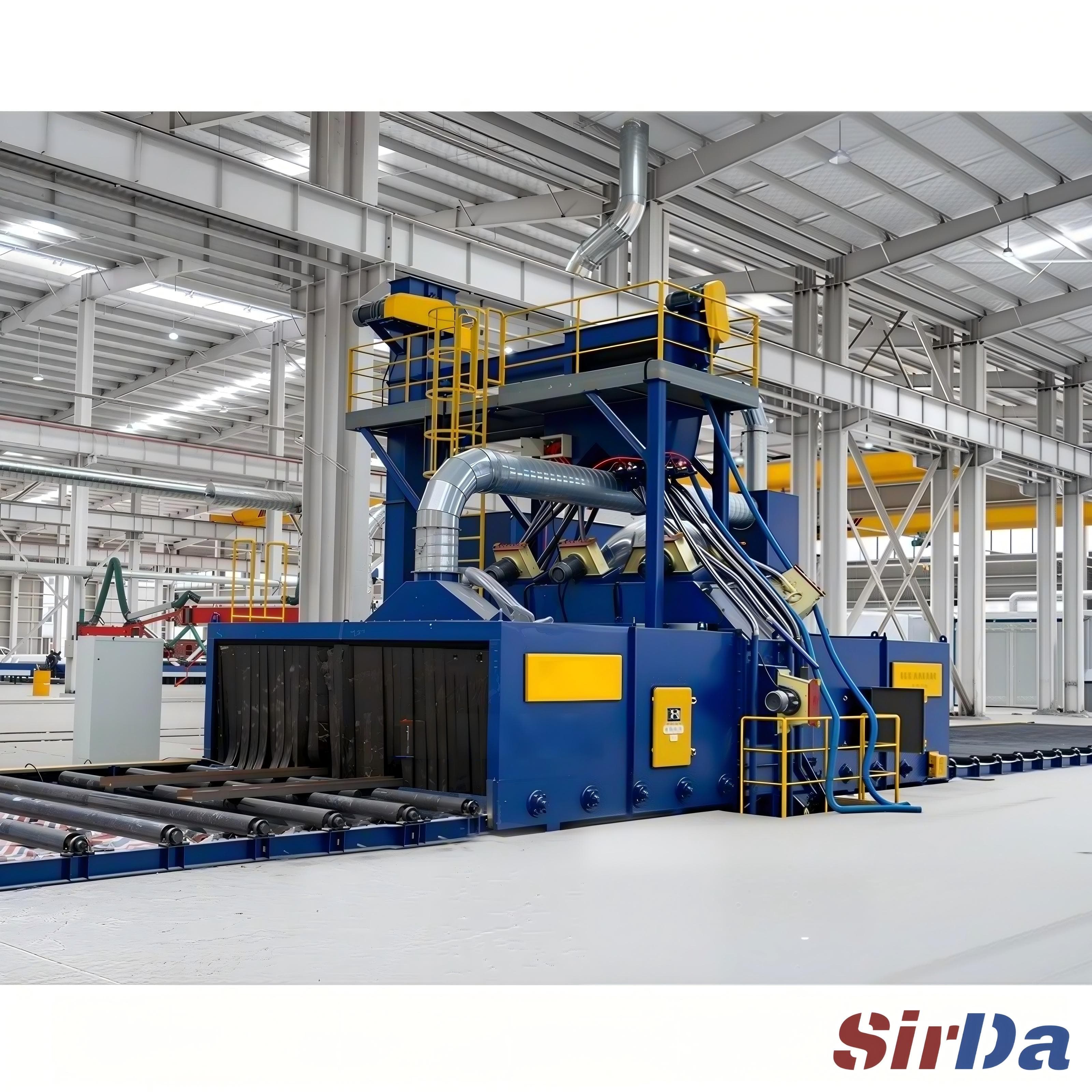
For some parts both families are wrong. Long sections, plate and structural profiles belong on a roller conveyor through-feed machine. Large or awkward fabrications with frequent changeover belong on a hanger or hook system. Aluminium and magnesium work needs an explosion-protected design, appropriate media and a suitable dust collection arrangement, specified up front rather than added after an inspection finding. And anything that cannot tolerate being handled twice forces the conveyor decision to be made on handling, not on cleaning.
The practical order of questions is short: can the part take impact, does it have blind geometry that a fixed position cannot reach, does it need a cosmetic surface, is the mix stable enough for single-layer loading, and does the volume justify a continuous line. Answer those in order and the conveyor choice usually makes itself.